Figure 1: Physics concepts map 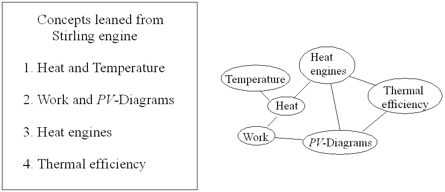
|
The Stirling heat engine is very rich with physics. At first glance the explanation of the Stirling engine and Stirling cycle
may appear simple, but as one investigates the details more carefully many nontrivial complexities arise. The Stirling engine
also has the benefit that enthusiastic students can attempt to design and build working engines which can vary from simple to very complex.
Figure 1 shows a map of some of the fundamental physics concepts that we can learn from the Stirling engine. This concepts will be explored in more detail below. |
| Heat , temperature, and work are the most fundamental concepts that can be learnt from the Stirling engine and cycle. It is essential to emphasize the difference between the meaning of heat and temperature. Heat is energy transferred from one body to another body due to a temperature gradient and temperature is simply describing the state of the matter, if it is cold or hot. | |
Figure 2: Piston 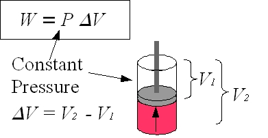
|
For an explanation of work, it is simplest to begin by defining work as the product of force on a body and the distance traveled by that body, W=F×d. Then, a cylinder with a cross sectional area A that contains a gas exerting a pressure P on a piston can be used as an example of work in a thermodynamic system. The force F acting on the piston due to the gas is F = P×A. When the piston moves a distance dx due to the force F, the work done by the gas W = Fdx = PAdx where Adx = dV is the change in volume. Although dV is the infinitesimal volume change, dV can be expressed as ΔV = V2–V1. W = P ΔV is work done in the volume change from V2 to V1 at constant pressure P. |
Figure 3: Two PV-diagrams 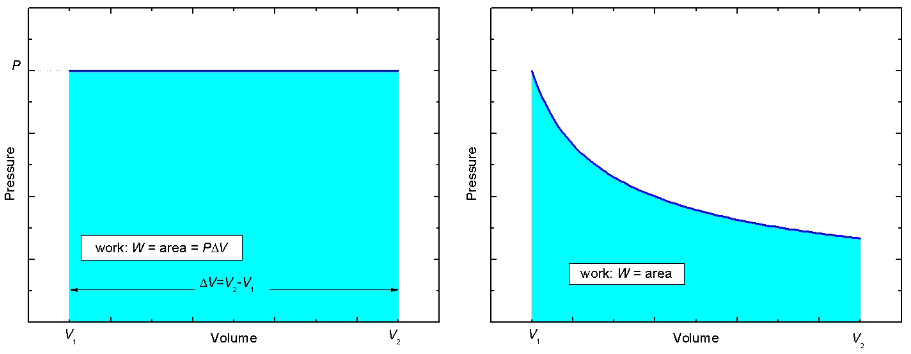
|
Now look at the pressure versus volume, or the PV-diagram, for this process shown in the left panel of Figure 3. Initially, the gas in the cylinder occupies a volume V1. Then the gas pushes the piston up while maintaining a constant pressure, P, until the gas occupies a volume V2 > V1. The PV-curve follows a straight path indicated by the dark blue line. Notice that the area beneath the curve, shaded light blue, is equal to P×ΔV which is just the work W done by the gas in the cylinder. It is true in general that the area beneath a curve in a PV-diagram, regardless of the shape, represents the work done. In the right side of Figure 3, the work done is equal to the area shaded light blue. |
Figure 4: Closed Loops 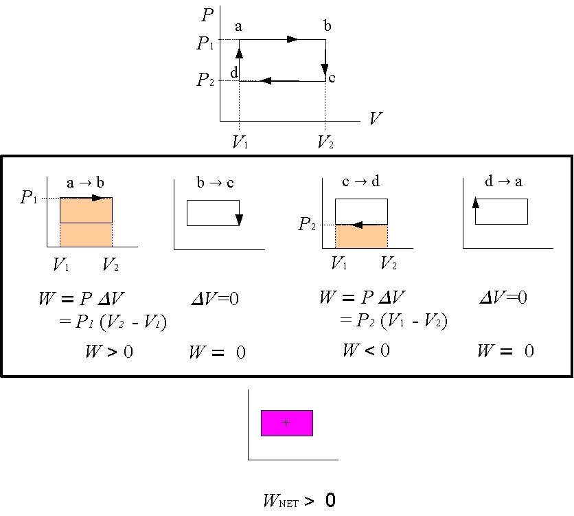
|
Now consider a closed loop that occurs in PV-diagrams of systems that repeatedly complete a cycle, such as a Stirling engine.
What is the total work done each cycle, i.e. once around the loop?
To answer this question, simply find the work done in each part of the cycle and then add them all up to get the total work. In the example in Figure 4 to the left, a rectangular cycle is completed in 4 steps. In going from a→b the volume changes from V1 to V2 > V1. The area beneath the curve, and hence the work done, is W=P1×(V2-V1) > 0. In processes b→c and d→a, the volume change ΔV=0 and so there is no work done, W=0. In going from c→d the volume changes from V2 to V1 < V2. The area beneath the curve, and hence the work done, is W=P2×(V1-V2) < 0. Notice that in this case the work done is negative. The negative sign means that work is done on the gas, and not by the gas.
To get the total, or net, work, just add up the work from each of the 4 processes. The net work done is just the area enclosed by the loop. This statement is true for any closed loop of any shape. |
Figure 5: Heat Engines 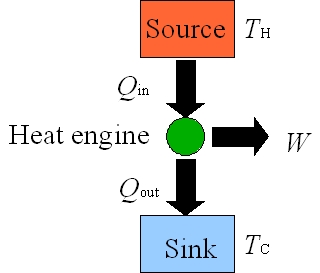
|
A heat engine is a device that converts the thermal energy into mechanical motion as it repeats a fixed sequence of steps. A schematic energy flow diagram for a common heat engine that operates between hot (TH) and cold (TC) reservoirs is shown in Figure 5. For each cyclic process, heat Qin is added from the hot reservoir at TH to the engine and the engine does work W by using that heat. Not all of the heat Qin is converted to work and the left over energy Qout = Qin – W leaves the engine and is dumped into the cold reservoir at TC. |
|
Thermal Efficiency
For each loop of the Stirling cycle, the work W done by the engine is the useful output when heat Qin is added to
the engine. In a perfect heat engine, all heat added to the system would be converted to work such that Qout = 0.
However, a perfect heat engine is not even theoretically possible (a consequence of the second law of thermodynamics)
and Qout is never zero, there is always rejected heat from the engine. It makes sense to define thermal efficiency of
a heat engine as ε = |W|/|Qin|. W is energy we get out of the engine and Qin is energy cost, or the energy put into the engine.
Because heat engines operate as a cycle, the initial and final internal energies for each complete cycle must be equal.
Thus, from the first law of thermodynamics, 0 = |Q|–|W| where |Q| is the net heat transferred and is given by |Qin|–|Qout|.
Therefore, the efficiency of an ideal Stirling engine is: ε = |W| / |Qin| = 1–|Qout| / |Qin|.
The First law of Thermodynamics
Consider the internal energy U of a gas from a microscopic point of view. Matter is made up of atoms and
molecules which have kinetic energies and potential energies. The internal energy of a gas includes both the kinetic energies of
all particles and potential energy of the interactions between them. The key point is that the potential energy
between the gas and the surrounding environment is not included in the internal energy of the gas.
Consider the following two situations:
(2) Gas in an enclosed cylinder expands by pushing on a piston. In this case, if no heat is
added to or removed from the system, the internal energy of the system decreases by an amount equal to the work done
by the system: ΔU = –W.
When both cases are considered simultaneously, the change in internal energy of a system is written as ΔU = Q – W.
This equation is the first law of thermodynamics. It should be emphasized that this law is based on careful experimental
observation.
|
|
created by Hiroko Nakahara
Hiroko.Nakahara@ubc.ca
last modified: February 18, 2012